13 May 2026 Disaster Recovery for the Cloudera Ecosystem using IBM Storage Scale
In enterprise systems, high availability is often discussed as if continuous service were guaranteed. However, as recent events have shown, even well-designed environments can be disrupted by factors far beyond our control.
Earlier this year there were outages ranging from a few hours to several weeks, not because of software failures, but due to physical damage and network disruptions. When primary systems go down, the problem quickly moves beyond technology and becomes a business crisis that can affect operations, customer trust, and the organisation’s reputation.
This is where a well-defined disaster recovery (DR) strategy becomes essential. It’s not just a safety net, but a way to ensure business continuity.
In this blog post, we’ll explore how a disaster recovery solution can be built for a Cloudera Data Platform environment using IBM Storage Scale, formerly IBM Spectrum Scale, and its Active File Management (AFM) capabilities for data replication. Based on a recent client engagement, we’ll show how this architecture helped to support continuity, reduce recovery risk, and keep critical data services available during a controlled DR switchover.
Disaster Recovery Basics
Disaster recovery refers to the strategies and processes used to restore critical systems, data, and applications after a failure.
Before we dive into the details, one thing to note is that the basic principles of DR remain the same across different environments. The goals are to get services back up quickly, minimise data loss, and keep the business running. The key objectives are:
- Minimal downtime, measured by the Recovery Time Objective (RTO). In this scenario, RTO depends largely on the time required to start the relevant services after the DNS or endpoint switch to the DR cluster.
- Minimal data loss, measured by the Recovery Point Objective (RPO). With IBM Storage Scale, this depends mainly on the AFM queue lag, which may range from seconds to minutes depending on the workload and replication status.
- Business continuity, achieved by restoring services quickly, minimising disruption, and protecting critical data. Although the tools and technologies may vary from one environment to another, the overall DR process usually follows the same structured sequence of steps.
Disaster Recovery Setup
Setting up a DR solution starts with building a reliable DR environment that can take over if the primary system fails.
The first critical step is to create a DR cluster that closely mirrors the production environment. Version alignment is essential to avoid compatibility issues during failover, especially for components such as compute and metadata services. Even small mismatches can lead to unexpected behaviour when the DR cluster is activated.
Along with the cluster setup, network and security configuration plays a key role. The DR environment must be reachable, properly secured, and integrated with existing enterprise controls. This includes:
- Network connectivity between production and DR.
- Firewall rules and access controls.
- DNS or load balancer configurations for traffic redirection.
- Consistent authentication and authorisation settings, including users, roles, and policies.
However, the most critical aspect of any DR setup is data replication: a DR cluster without up-to-date data is of limited value. The goal is to ensure that data from the production environment is continuously or periodically replicated to the DR site. This applies across several layers:
- Storage
- Metadata
- Ingestion
- Security
- Governance
Each service may use a different replication mechanism, but they must work together to ensure the DR environment reflects the latest possible state of production.
A typical Cloudera environment consists of multiple services, each of which plays a critical role in the overall data platform. When planning disaster recovery, it’s not enough to focus only on storage; a clear strategy is needed for every layer of the stack. The following sections outline the key services and the usual DR approach for each of them:
1. Storage Layer: HDFS/Ozone/IBM Storage Scale
This is where the data itself resides, so the storage layer is the foundation of any DR strategy.
- Use Cloudera Replication Manager for HDFS and Ozone replication between clusters.
- Schedule replication jobs, preferably using incremental replication where possible.
- For large environments, consider DistCp-based optimisations or storage-level replication through AFM for external storage systems such as IBM Storage Scale.
This layer defines RPO, so replication frequency matters. In our client’s case, the setup included IBM Storage Scale as the data storage layer.
2. Metadata Layer: Hive Metastore
Even if the data itself has been replicated, the system is unusable without consistent metadata.
- Replicate Hive databases and tables using Cloudera Replication Manager.
- Ensure that external table paths are consistent across production and DR.
- Back up and restore the metastore database (MySQL or PostgreSQL) as an additional safety layer.
Always validate metadata consistency after replication.
3. Ingestion Layer: Kafka/NiFi
This is where new data enters the system, so the DR strategy here is crucial.
- Kafka:
- Use MirrorMaker 2.0 for topic replication.
- Replicate topics, partitions, and consumer offsets.
- NiFi:
- Export and import flow definitions.
- Use NiFi Registry for version-controlled pipelines.
- Maintain DR-ready configurations.
The objective is to ensure that ingestion can resume quickly in the DR environment without data loss or duplication.
4. Security Layer: Ranger
Security policies must remain consistent across clusters.
- Use Ranger export/import APIs to synchronise policies.
- Ranger replication policies can also be used within Cloudera Replication Manager.
- Automate policy replication at regular intervals.
- Validate user and group mappings, including LDAP or AD integration.
Missing or inconsistent policies in the DR environment can prevent access, even when the data, metadata, and services are otherwise available.
5. Governance Layer: Atlas
Metadata governance and lineage are often overlooked in DR planning, but they are important for compliance and visibility.
- Backup and restore the Atlas database (commonly PostgreSQL).
- Atlas replication policies can be used to replicate the metadata and data lineage for Hive external tables, Iceberg tables, and other Atlas-supported entities.
- Export and import metadata where needed.
- Ensure that integration with Hive and Spark is re-established in the DR environment.
This layer is key for compliance, auditability, and data lineage visibility.
IBM Storage Scale/GPFS: An Alternative to Traditional HDFS
Before looking at the switchover process, it is worth clarifying the additional challenge in Cloudera environments that use IBM Storage Scale, formerly IBM Spectrum Scale/GPFS, instead of traditional HDFS storage. In a typical Cloudera ecosystem, storage is usually handled in one of two ways:
- HDFS (the default storage within Cloudera clusters): With HDFS storage, we typically use Cloudera Replication Manager to replicate or synchronise data from production to the DR cluster. Depending on the use case, it can also be used to replicate Ozone data and Hive metadata.
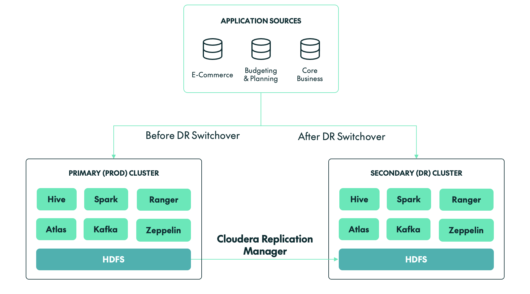
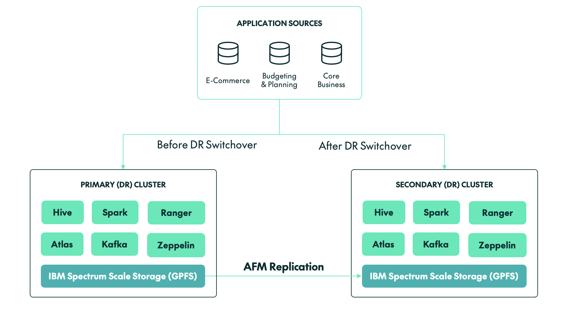
- IBM Storage Scale/GPFS: If IBM Storage Scale is being used as the storage layer for a Cloudera cluster, then we must use AFM, a storage-level replication tool provided by IBM to synchronise data from production to the DR cluster in near-real time.
Unlike many traditional Hadoop deployments, our client’s environment did not rely on HDFS for storage. Instead, the backbone of the client’s platform was IBM Storage Scale/GPFS, a high-performance shared file system offering scalability and flexibility beyond conventional Hadoop storage layers.
While this brought clear advantages in terms of performance and integration, it also introduced additional considerations for disaster recovery:
- DR could no longer depend solely on native Hadoop replication mechanisms such as DistCp or Cloudera Replication Manager.
- Storage-level consistency had to be validated independently.
- Failover required coordination across both compute and storage layers.
Switchover Strategy: GPFS + AFM
With IBM Storage Scale and AFM, the switchover approach differs from traditional HDFS setups; there is no separate final replication step.
Instead, the focus is on confirming that the DR side is already synchronised before the switch is made. In this case, we validated that the AFM cache was fully synchronised, with no pending asynchronous writes and no queue backlog.
Once data consistency had been confirmed, the AFM roles were switched, allowing the DR storage layer to take over as the active source. At that point, the DR environment was ready to operate as the new primary environment.
Disaster Recovery Switchover Process
A typical disaster recovery process includes these steps:
- Incident detection and impact analysis: Identifying the failure, whether it affects the cluster, storage, network, or full data centre. This also involves assessing which systems and services are affected, estimating potential data loss and downtime, and formally triggering the DR process.
- Pausing data ingestion: Stopping upstream data pipelines, including streaming and batch processes, to prevent inconsistent or partial data writes.
- Validation of DR readiness: Ensuring that the DR environment is available, properly configured, and has the latest replicated or backed-up data and metadata.
- Data consistency checks: Verifying that the data in the DR environment is complete and usable before activation.
- Activation of the DR cluster: Starting core services such as storage, resource management, query engines, and metadata services.
- Application and traffic redirection: Updating DNS, load balancers, or endpoints to route users and applications to the DR environment.
- System and data validation: Running test queries, jobs, and checks to confirm that the environment is functioning as expected.
- Resuming data pipelines: Restarting ingestion and processing jobs, while monitoring for delays or backlogs.
- Monitoring: Keeping stakeholders informed while continuously monitoring system health, performance, and stability.
Although the above steps provide a general framework, the actual execution can vary significantly depending on the technologies involved, especially when storage and replication mechanisms differ. The following section describes the switchover process used for a Cloudera cluster backed by IBM Storage Scale/GPFS and AFM.
DR Switchover for a Cloudera Cluster
Once the DR cluster had been fully set up and configured, a controlled DR switchover was initiated to validate the strategy. The process followed a step-by-step approach to ensure a consistent and reliable transition.
Step 1: Freeze Production
The first step, before making any changes to the environment, was to ensure that no new data was entering the system.
Stop new onboarding activity
No new user access requests, Hive tables, or NiFi flows were permitted during the 24 hours before the switchover.
Stop ingestion pipelines
All batch and streaming jobs were stopped. A clean cutover is not possible if a Spark job is halfway through a multi-terabyte shuffle or if streaming pipelines are still writing data.
Cluster activity snapshot:
- Active YARN applications: 0
- Kafka consumer lag: 0
- Running Spark jobs: 0
Step 2: AFM Synchronisation Validation
This was the most critical step in the GPFS-based DR process.
AFM state check:
# mmgetstate -a
Node State:
node1 active
node2 active
AFM fileset status:
State: Active
Queue Length: 0
Pending Ops: 0
AFM queue verification:
# mmafmctl fs1 getstate
Fileset: /gpfs/data
Mode: Primary
Gateway: node1
Queue Length: 0
Dirty Data: 0 bytes
This confirmed that there was no replication lag.
Hive and Ranger metadata was backed up to a GPFS location using database backup commands and then synchronised using AFM. Once synchronised, these backups can be restored in the DR environment.
Step 3: Filesystem Consistency
The next step was to ensure that no dirty cache data remained.
Flush operation:
# mmfsctl fs1 syncFS
Result: SUCCESS
Disk usage validation:
Production Cluster | DR Cluster | |
|---|---|---|
| # mmdf fs1 Used: 18.7 TB | # mmdf fs1 Used: 18.7 TB |
Step 4: Switchover Execution
We then transitioned control to the DR environment:
- The production cluster was stopped.
- The AFM target was prepared for active access.
- DR cluster services were started.
Step 5: Endpoint Switching
The JDBC/ODBC, Kafka, and NiFi endpoints were updated so that services were redirected to the DR cluster.
Old Endpoint | New Endpoint | |
|---|---|---|
| jdbc:hive2://prod-cluster:10000 | jdbc:hive2://dr-cluster:10000 |
DNS propagation was completed in approximately 3 minutes.
Step 6: Validation
The next step was to validate the Hive table records and the number of files in the HDFS/GPFS locations, ensuring that both matched the source cluster. We also tested whether Kafka could successfully produce and consume data on the DR cluster.
Data validation:
SELECT COUNT(*) FROM transactions;
Before: 98,245,112
After: 98,245,112
Filesystem check:
ls /gpfs/data/warehouse | wc -l
= 1,245,332 files (matched the source cluster)
Ingestion test:
Kafka → GPFS write: SUCCESS
Hive table refresh: SUCCESS
Final metrics achieved:
Metric | Target | Achieved |
|---|---|---|
| RTO | 45 min | 40 min |
| RPO | ~5 min | ~0 min |
| Data loss | >0 | 0 |
Challenges During the DR Switchover
Whilst the DR switchover was successful overall, we encountered two important performance challenges that are worth highlighting for teams working with a Cloudera/GPFS setup:
Hive Query Delays due to GPFS Tracing
Issue: During post-switchover validation, several Hive queries took unusually long to complete or appeared to hang, especially queries involving large table scans or metadata-heavy operations.
Root cause: After investigation, the issue was tracked back to tracing being enabled on the GPFS filesystem.
- GPFS tracing introduced additional overhead on filesystem operations.
- Cloudera services rely heavily on file listing operations through HDFS APIs over the GPFS mount.
- Commands such as hdfs dfs -ls and metadata scans became significantly slower.
- This directly impacted Hive query planning and execution time.
Resolution:
- GPFS tracing was disabled on the affected filesystem.
- Affected services, including Hive and Impala where required, were restarted.
- The improvement was validated using filesystem listing benchmarks.
Small-File Problem Affecting Query Performance
Issue: We also identified a large number of small files in critical Hive tables after the switchover, which led to:
- Increased metadata load.
- Slower query execution.
- Higher resource utilisation.
Root cause:
- Continuous ingestion pipelines were generating small files.
- No compaction or merge strategy had been applied before the switchover.
- GPFS handles metadata differently from HDFS, amplifying the impact.
Resolution: We applied several optimisation techniques:
- Hive major compaction and file merge operations were performed.
- INSERT OVERWRITE was used to rebuild large tables with optimised file sizes.
- Ingestion pipelines were tuned to generate larger, more efficient file sizes, typically around 128 MB to 512 MB.
What Made the Switchover Successful
The following factors contributed to the successful execution of the Cloudera DR switchover:
- Deep understanding of GPFS and AFM behaviour
AFM is asynchronous by nature, which means there can be lag between the primary and DR sites. Understanding concepts such as queue backlog, cache state, and write behaviour is critical during a switchover. For example, knowing when the DR side is truly synchronised and healthy can mean the difference between a clean recovery and data inconsistency.
- Strict validation of filesystem-level consistency
Before initiating any switchover, it is essential to validate that:
- All replication queues have been cleared.
- No pending writes remain.
- The DR filesystem reflects the latest state of production.
This step cannot be skipped or rushed. Even a small inconsistency at the storage layer can propagate upwards, affecting Hive tables, Spark jobs, and downstream analytics.
- Clear separation of storage and compute switchover
One of the key advantages of this architecture is the decoupling of storage and compute. However, this also introduces the need for careful coordination. The storage layer, based on GPFS and AFM, must be stable and ready before compute services are brought online. If compute services start too early, they may read incomplete or inconsistent data.
- Strong coordination across teams
A successful DR event is not just a technical exercise, but a coordinated effort across multiple teams.
- The infrastructure team validates storage and replication.
- The platform team manages Cloudera services.
- The network team handles DNS and routing.
- The application team verifies business functionality.
Timing and communication are critical, as delays or misalignment between teams can increase downtime or introduce errors during recovery. Having a clear runbook, defined responsibilities, and real-time communication ensures that everyone is aligned when it matters most.
Conclusion
A DR switchover is not just a technical activity; it is a critical business continuity exercise. With proper planning, validation, and execution, organisations can support controlled transitions while reducing operational risk.
By following structured procedures, maintaining synchronisation between clusters, and addressing known challenges proactively, teams can handle both planned switchovers and real disaster scenarios with greater confidence.
At ClearPeaks, we specialise in designing and implementing disaster recovery strategies for complex data platforms, including Cloudera environments. We help organisations to build production-grade DR architectures, implement and optimise replication strategies, conduct low-risk DR drills and controlled switchovers, align RTO and RPO with business goals, and create runbooks, automation, and monitoring frameworks. Whether you are setting up DR for the first time or validating an existing setup, our experts will ensure that your systems are not just configured, but truly ready.