09 Nov 2022 Running Apache Airflow Workflows on a Kubernetes Cluster
Apache Airflow is a platform which enterprises use to schedule and monitor workflows running on their infrastructures, providing a high level of observability to users and sysadmins.
In this series, our goal is to show how to deploy Apache Airflow on a Kubernetes cluster, to look at the options for making it secure, and to make it production-ready.
In our first blog post, we demonstrated how to build the required Kubernetes resources to deploy and run Apache Airflow on a Kubernetes cluster. In this second part, we will demonstrate how to make Airflow on Kubernetes ready-to-run workflows (Directed Acyclic Graphs – DAGs) using Kubernetes Executor, and we will also show you how to monitor developed workflows using the Apache Airflow webserver UI.
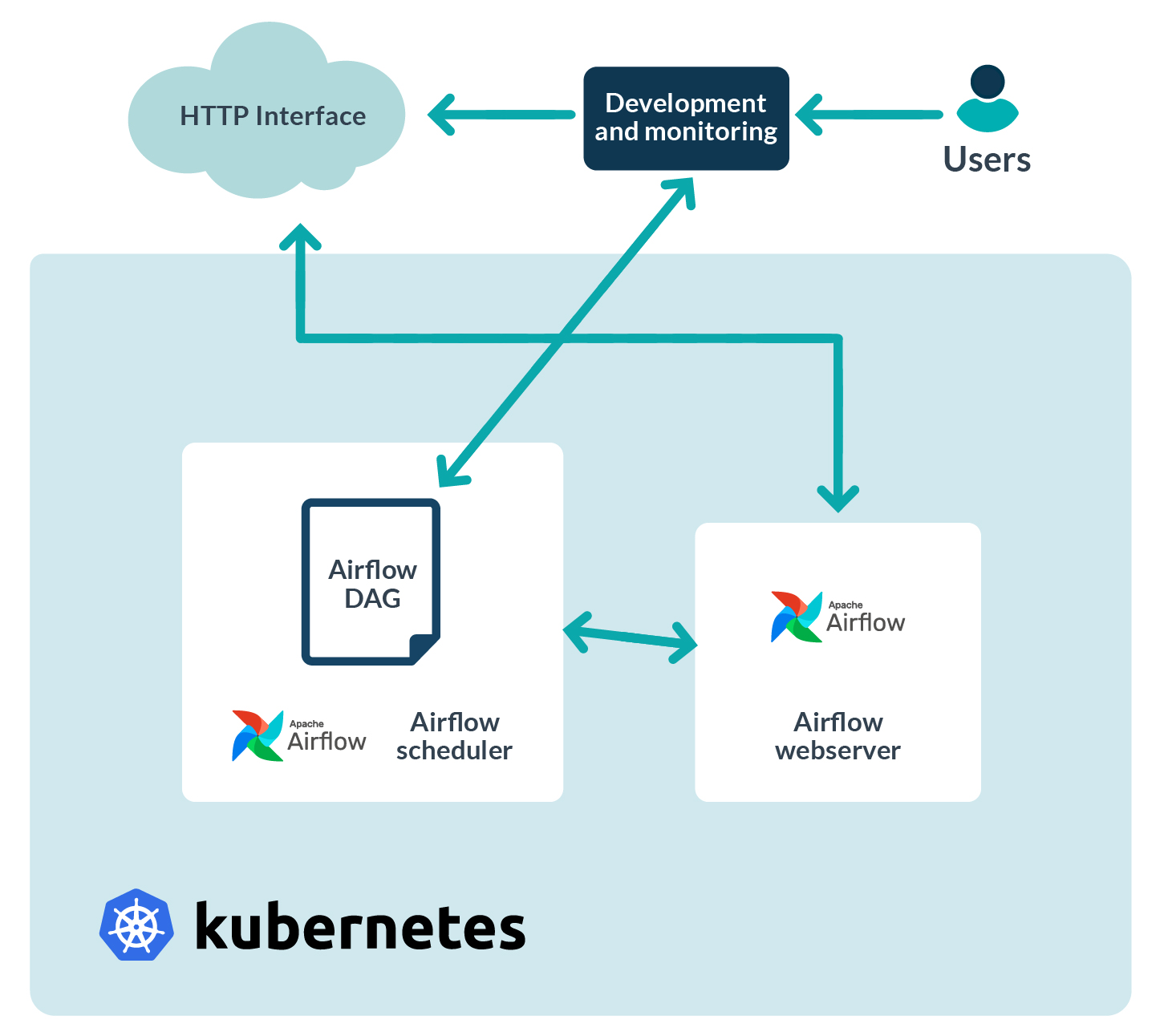
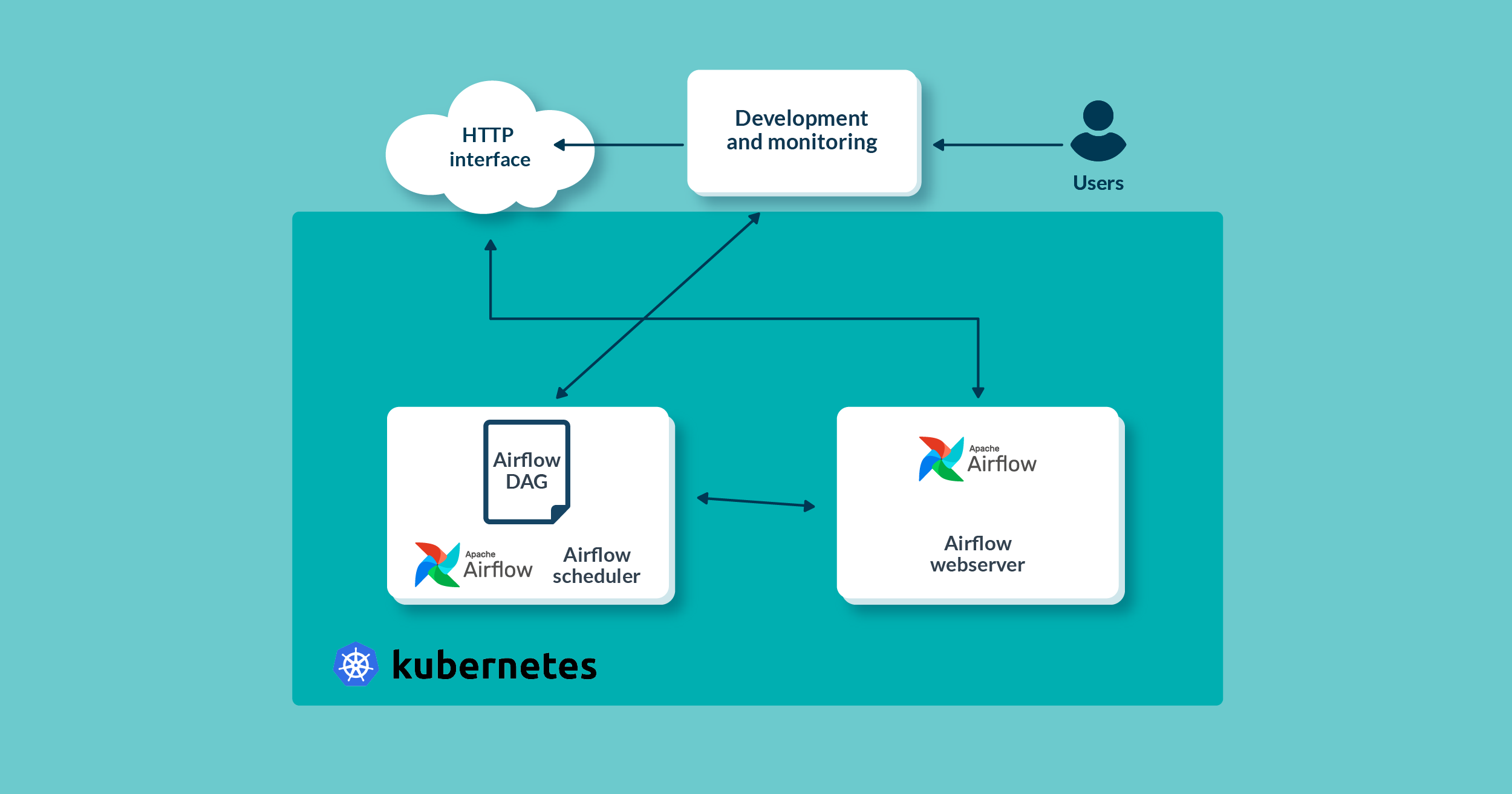
Figure 1: Architecture blocks
Configuring Kubernetes Executor
In the previous blog post, we configured Airflow to use Kubernetes Executor when running task instances from the DAG, by setting the environment variable of the Airflow Pod to ‘KubernetesExecutor’.
This, however, is not enough for Airflow to leverage Kubernetes Executor when there is a big demand for ‘power’. The Kubernetes server needs to know how to dynamically provide more worker Pods if there are a lot of task instances from the DAG, so we need to configure Kubernetes Executor with a custom Pod template file, which will be used by the Kubernetes server when creating worker Pods.
According to the Apache Airflow documentation, this can be done by either:
- Setting the value of the environment variable
‘AIRFLOW__KUBERNETES__POD_TEMPLATE_FILE’
to the path of the Pod template file, or
- Setting the Pod template file path in the Airflow configuration file in the ‘kubernetes’ section.
In our case, we took the second approach. The Airflow configuration file is located on the AIRFLOW_HOME path, usually on /opt/airflow/airflow.cfg, as shown in the picture below. There, we specified the path to pod-creator.yaml, our custom Pod template file, also visible below:
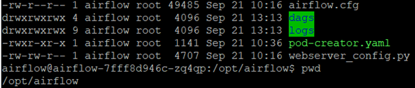
Figure 2: Airflow home folder structure
Kubernetes will use that file to spawn the worker Pods when the Airflow workflow is triggered. The Pod template file is similar to the Airflow deployment file from the previous blog post (airflow-deployment.yaml), and its content is shown below:
---
apiVersion: v1
kind: Pod
metadata:
  name: airflow-worker
  namespace: airflow
spec:
  containers:
    - name: base
      imagePullPolicy: IfNotPresent
      image: 'apache/airflow:2.3.4'
      env:
      - name: AIRFLOW__CORE__SQL_ALCHEMY_CONN
        value: "postgresql://admin:test123.@postgres:5432/postgresdb"
      - name: AIRFLOW__CORE__EXECUTOR
        value: "LocalExecutor"
      - name: AIRFLOW__KUBERNETES__NAMESPACE
        value: "airflow"
      - name: AIRFLOW__CORE__DAGS_FOLDER
        value: "/opt/airflow/dags"
      - name: AIRFLOW__KUBERNETES__DELETE_WORKER_PODS
        value: "True"
      - name: AIRFLOW__KUBERNETES__DELETE_WORKER_PODS_ON_FAILURE
        value: "True"
      volumeMounts:
        - name: logs-pv
          mountPath: /opt/airflow/logs
        - name: dags-pv
          mountPath: /opt/airflow/dags
  restartPolicy: Never
  securityContext:
    runAsUser: 50000
    fsGroup: 50000
  serviceAccountName: "airflow-scheduler"
  volumes:
    - name: dags-pv
      persistentVolumeClaim:
        claimName: dags-pvc
    - name: logs-pv
      persistentVolumeClaim:
        claimName: logs-pvc
It’s important when defining this YAML file to set the container name to the value ‘base’, and to define which image will be running inside that container (this is explained in the Airflow official documentation at this link).
In our case, the image containing Apache Airflow version 2.3.4 will be downloaded from the internet and imported into the worker Pod. To do so, we need to set the ‘containers’ keyword in the YAML file above to the value ‘base’ and we need to set the ‘image’ keyword to the value ‘apache/airflow:2.3.4’.
The rest of the specifications are related to the Airflow Executor and persistent volumes. With this Pod template file, our Airflow worker Pod will run an Apache Airflow version 2.3.4 container and it will run LocalExecutor. This is enough for the worker Pod to run delegated tasks from the Airflow workflow, which we will develop and describe in the following sections.
Airflow Workflow Example
Now that our Apache Airflow environment is ready, we can start creating Apache Airflow workflows. Every Airflow workflow consists of tasks (regular Python functions or Airflow operators) that are executed by the scheduler in sequential order (so Apache workflows are also called DAGs – Directed Acyclic Graphs).
Note that Airflow tasks are not where the actual data processing – or any work at all – takes place: tasks are only definitions of the work that needs to be done, while the actual processing is done on some other machines or services which are integrated from the workflow code. From the Airflow workflow, we need to invoke these machines or services to trigger the task (in our case, we need to give that task to a Kubernetes worker Pod).
To do so, we can use Airflow Operators. Operators are like Python packages, developed by the community and other independent professionals, making Airflow a very flexible framework to schedule tasks and to integrate with various systems and services. Airflow comes with some pre-installed operators, suitable for all research and development purposes.
For our demonstration, we created one simple Airflow workflow which downloads CSV files from the internet and saves the data to the PostgreSQL database, also running on a Kubernetes cluster. After the data has been saved into temporal staging tables, a cleaning process is triggered to wipe duplicates and update existing values with the latest data. We use a PostgresOperator to perform these tasks, which can be used to run SQL queries directly on a PostgreSQL database.
We will now explain the Airflow workflow code, piece by piece, and then we will show you how to trigger, monitor and inspect an Airflow workflow running on a Kubernetes cluster.
Importing the Required Packages
The first thing to define in the header of our workflow file are the Python packages that we are going to use throughout the script. They are shown below:
import datetime
import pendulum
import os
import requests
from airflow.decorators import dag, task
from airflow.providers.postgres.hooks.postgres import PostgresHook
from airflow.providers.postgres.operators.postgres import PostgresOperator
As we will be doing some date and time manipulations to schedule the Airflow workflow, we imported the datetime and pendulum packages; the requests package is used to download the CSV data file from the internet.
The dag and task packages are required respectively to define metadata about the workflow (how it will run and be scheduled) and to define the tasks themselves (the actual work they will do). We will demonstrate below how to use these packages in the code.
Finally, the tasks which define the queries that will be executed on top of a PostgreSQL database will use the PostgresHook and PostgresOperator packages.
Defining the Workflow Metadata
The next thing to define is the Airflow workflow metadata, which describes how and when the workflow will run. It uses the @dag decorator which we mentioned above. The workflow metadata is shown below:
@dag(
    schedule_interval=”0 0 * * *”,
    start_date=pendulum.datetime(2021, 1, 1, tz=”UTC”),
    catchup=False,
    dagrun_timeout=datetime.timedelta(minutes=60),
    tags=[‘Employee_cleaning’],
    description=”Clean employee data”,
)
Our workflow will run every day at midnight, as defined with a CRON expression in the schedule_interval variable.
The workflow start date is set to 2021/01/01 and catchup is set to false, which means that Airflow should not execute all workflow runs from the start date until today, when we manually trigger the workflow to inspect its execution.
Workflow timeout is set to one hour, which means “do not fail the whole workflow for 60 minutes if some of the tasks failed”.
The last two variables are used for the Airflow webserver UI: a tags array to filter the workflows in the UI list, and a description that will be shown alongside the workflow label in the UI.
Defining the tasks
Now we are getting close to the most important part of the workflow – task definitions. In our workflow we have a total of four tasks: two of them are using Airflow operators (PostgresOperator), defined in the regular Python function called etl_cleaning(), which will be used to instantiate the DAG. The other two use the Airflow TaskFlow API decorator @task, which enables the writing of Airflow tasks as plain Python functions.
The first two tasks, part of etl_cleaning(), are shown below:
Def etl_cleaning():
    create_employees_table = PostgresOperator(
        task_id=”create_employees_table”,
        postgres_conn_id=”pg_conn”,
        sql=”””
            CREATE TABLE IF NOT EXISTS employees (
                “employee_id” NUMERIC PRIMARY KEY,
                “company_name” TEXT,
                “employee_marker” TEXT,
                “description” TEXT,
                “leave_days” INTEGER
            );”””,
    )


    create_employees_temp_table = PostgresOperator(
        task_id=”create_employees_temp_table”,
        postgres_conn_id=”pg_conn”,
        sql=”””
            DROP TABLE IF EXISTS employees_temp;
            CREATE TABLE employees_temp (
                “employee_id” NUMERIC,
                “company_name” TEXT,
                “employee_marker” TEXT,
                “description” TEXT,
                “leave_days” INTEGER
            );”””,
    )
The first task (create_employees_table) creates a PostgreSQL table called employees, using the connection to the PostgreSQL database defined in the connections section of the webserver UI (we will cover how to add a PostgreSQL connection later in this article). The employees table will be the final table in which the downloaded CSV data will be saved.
The second (create_employees_temp_table) creates a table called employees_temp with the same PostgreSQL connection. The employees_temp table serves as a stage table for the initial data load, before cleaned and processed data is saved into the employees table.
The last two workflow tasks are the main tasks which do the work, loading and cleaning the CSV data. The @task decorator tells Airflow that they are going to be tasks, so that it can create instances to be run by the Executor (in our case, a Kubernetes Executor); they are shown below:
@task
    def get_data():
        # NOTE: this is going to be saved in Persistent Volume – visible from the K8S host
machine
        data_path = “/opt/airflow/dags/files/employees.csv”
        os.makedirs(os.path.dirname(data_path), exist_ok=True)

        url = “https://raw.githubusercontent.com/apache/airflow/main/docs/apache-airflow/
tutorial/
        pipeline_example.csv”

        response = requests.request(“GET”, url)


        with open(data_path, “w”) as file:
            file.write(response.text)


        postgres_hook = PostgresHook(postgres_conn_id=”pg_conn”)
        query = “””
        COPY employees_temp
        FROM STDIN
        WITH CSV HEADER DELIMITER AS ‘,’ QUOTE ‘\”’
        “””
        conn = postgres_hook.get_conn()
        cur = conn.cursor()
        with open(data_path, “r”) as file:
            cur.copy_expert(
                query,
                file,
            )
        conn.commit()


    @task
    def merge_data():
        query = “””
            INSERT INTO employees
            SELECT *
            FROM (
                SELECT DISTINCT *
                FROM employees_temp
            ) q1
            ON CONFLICT (employee_id) DO UPDATE
            SET employee_marker = excluded.employee_marker,
            company_name = excluded.company_name,
            leave_days = excluded.leave_days;
        “””

        try:
            postgres_hook = PostgresHook(postgres_conn_id=”pg_conn”)
            conn = postgres_hook.get_conn()
            cur = conn.cursor()
            cur.execute(query)
            conn.commit()
            return 0
        except Exception as e:
            print(“SQL query error – “ + str€)
            return 1
The first task downloads the employee data from the provided link, saves it in the local filesystem, and loads it into employees_temp.
The second selects distinct records from the employees_temp table and loads them into the employees table, while also updating existing records.
Note that these two tasks use the PostgresHook modules instead of PostgresOperator, which means that the Python package psycopg2 is running under the hood to execute SQL queries – this enables the execution of row-by-row queries.
Finally, the last two lines of the Airflow workflow define dependencies between the tasks and instantiate the workflow (DAG) by calling the etl_cleaning() function; the lines are shown below:
[create_employees_table, create_employees_temp_table] >> get_data() >> merge_data()
dag = etl_cleaning()
Based on the above expression, the workflow DAG will be translated into a series of dependent tasks in the following order:
- The tasks create_employees_table and create_employees_temp_table do not depend on each other.
- The task merge_data depends on the task get_data.
- The task get data depends on the tasks create_employees_table and create_employees_temp_table (but both tasks need to finish successfully before get_data can start).
Executing the Airflow Workflow
Earlier, we saw what the Airflow home folder looks like: inside there are two folders, dags and logs.
The dags folder serves as the location where we need to put Airflow workflows (DAGs) to be able to execute them from the webserver UI; we put our developed Airflow workflow here. In the picture below you can see the contents of the dags folder. Among other workflows being tested we can see our own developed workflow, contained in a Python file called clean_data.py; that file contains all the code shown in the previous section.
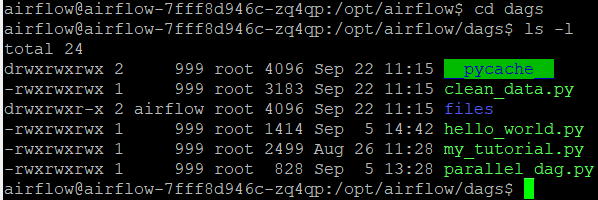
Figure 3: Airflow DAGs folder
After putting the workflow file in the dags folder, the workflow will show up in the webserver UI list after a few minutes, as shown below:
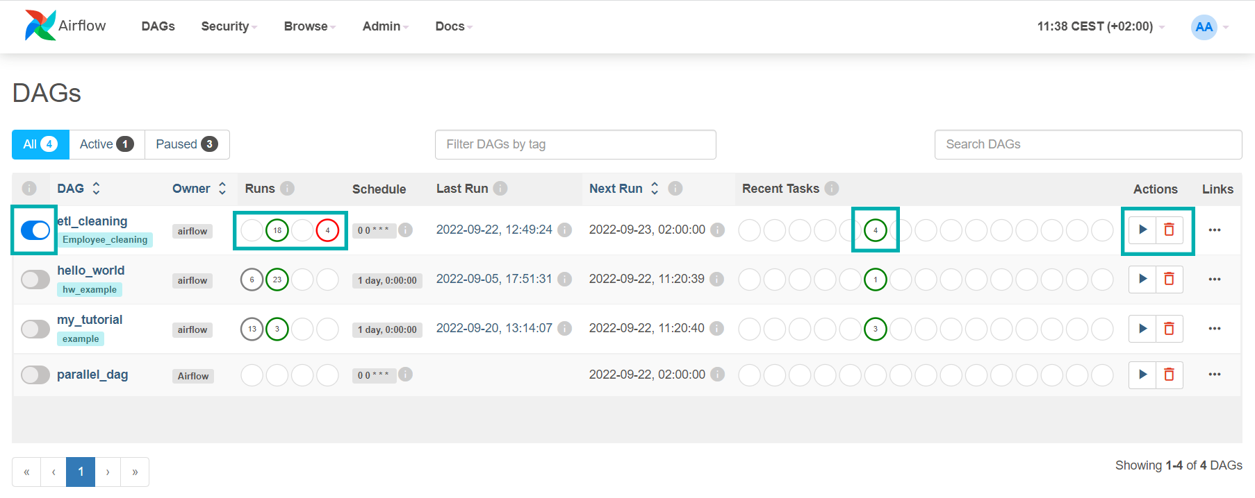
Figure 4: Airflow webserver UI
In the picture above we have marked some parts of the web UI: on the far left there is a small toggle button which is used to pause or resume the workflow; when the workflow is paused, no runs will be scheduled for it. The other marked parts are the info about recent successful or failed workflow runs. In our case, there were a total of 18 failed runs and a total of 4 successful runs. On the far right there is a small Play button which allows you to execute the workflow manually.
Note that our workflow in the webserver UI is called etl_cleaning, because this is the name we gave to the object of the DAG in the workflow code. The name of the workflow file itself (clean_data.py) is not used to list the workflow in the webserver UI.
Before executing our workflow, there is one more step to be taken: adding the PostgreSQL connection string through the webserver UI. From the menu bar of the webserver UI, we go to Admin and then Connections, as shown in the picture below:
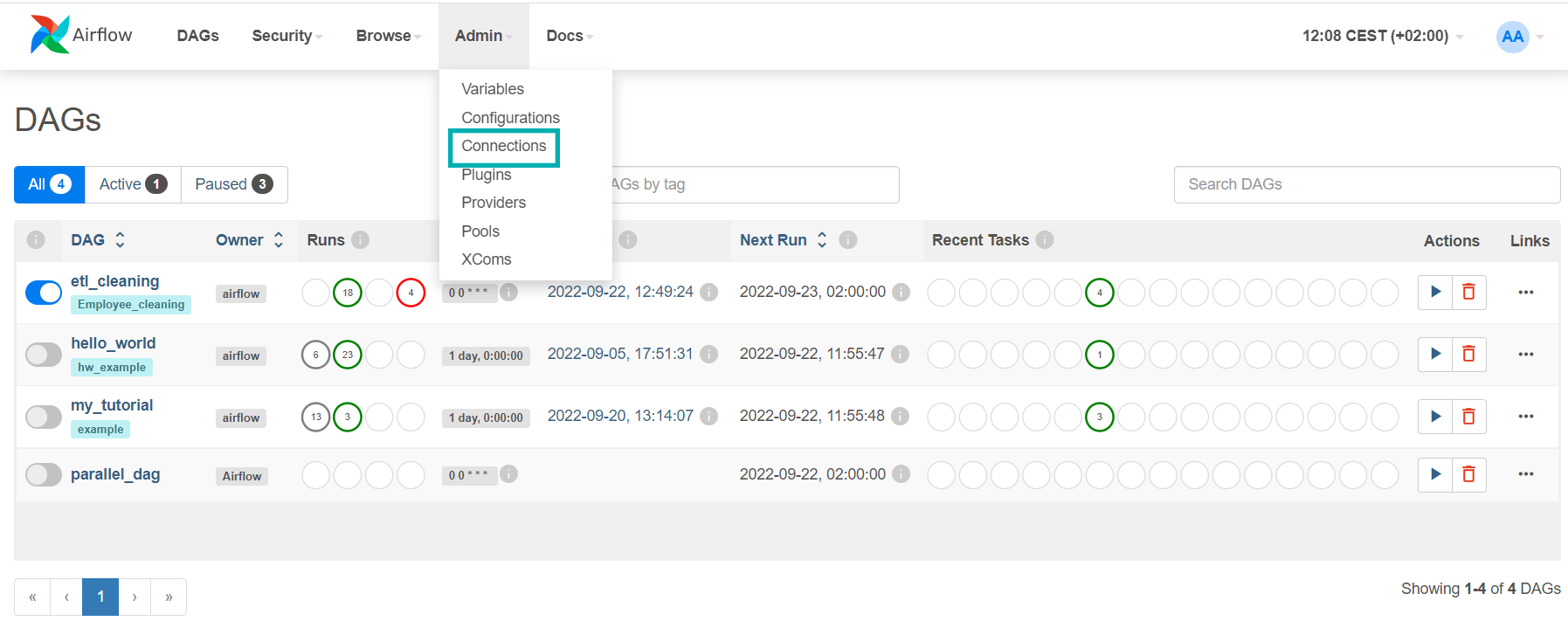
Figure 5: Airflow Connections view
In the Connections view, select the small ‘+’ button on the upper left to add a new connection string, like the one used by PostgresOperator and PostgresHook in our workflow script. Each connection string is identified by a ‘Connection Id’ field, which is the one used in the script to reference the connection. Below, we can see an example of the form to add a new connection:
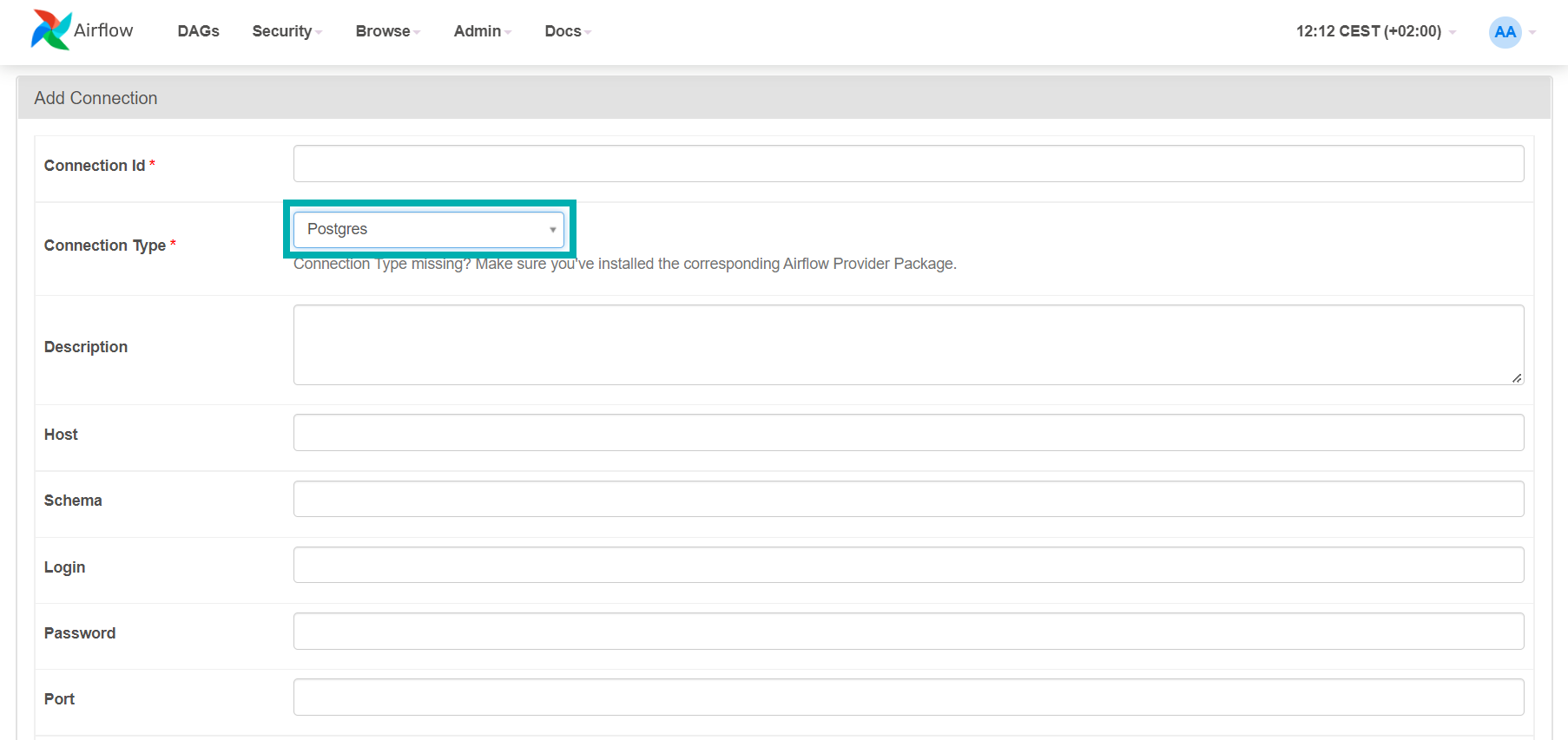
Figure 6: Adding a new Airflow connection
In our case, we populated the fields as follows:
- Connection Id: pg_conn (as referenced in the tasks)
- Connection Type: Postgres
- Host: postgres (name of the Kubernetes Postgres service running on the Pod)
- Schema: postgresdb (name of the database)
- Login: <username to access postgres>
- Password: <password>
- Port: 5432
After defining the PostgreSQL connection string, we started the workflow by using the Play button and the tasks from the workflow file started to run in their order of dependency.
Thanks to the webserver UI, we were also able to monitor the execution of the workflow and its tasks; we will show you how in the following section.
Monitoring Airflow Workflows
Now it’s time to explore the Airflow webserver UI and look at the many ways to monitor our Airflow workflows and inspect execution failures.
By clicking on the name of our running workflow, we open a monitoring view, depicted below:
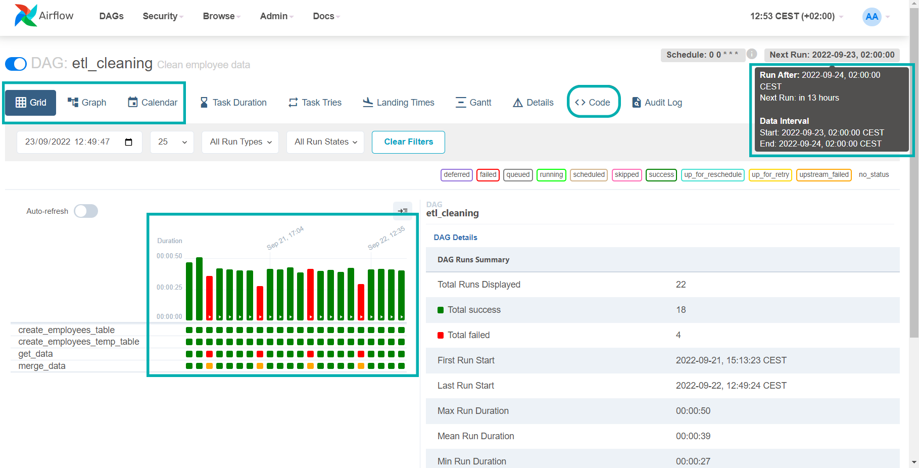
Figure 7: Monitoring Airflow DAGs
We have marked the views where we can inspect the status of the workflows. In the red and green bar chart, we can see a nice representation of the past workflow runs. The colour of the bar represents the final status of the execution (green if successful, red if failed), while its height shows the task duration, giving a very clear visual representation of the execution history.
In the upper right we can see the workflow scheduling information. As our workflow is scheduled to run every day at midnight, in the web UI we can see that the next run will happen on 2022-09-23 at 2 AM (local time). Note that the Next Run for Apache Airflow means the start of the scheduled interval, not the moment when the workflow will be triggered.
In this example, the actual workflow would start before the next scheduled run (on 2022-09-24, 02:00:00, as indicated by the Run After value). This is a design choice, explained with the logic of batch data processing – Apache Airflow will always wait for data that needs to be processed or stored before its tasks are started; this needs to be borne in mind when developing workflows.
Finally, in the upper left of the picture we can see two more views where we can monitor the workflow execution: Graph and Calendar.
The Graph view shows us the workflow tasks and their dependencies in the form of a DAG, as shown below:
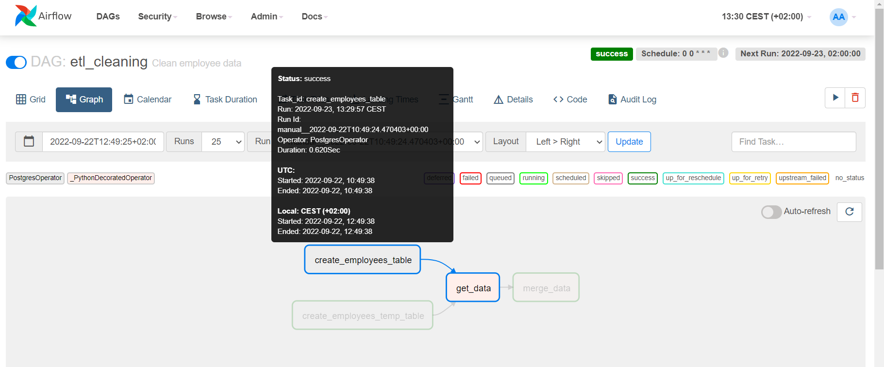
Figure 8: Inspecting workflow details
If you hover with the mouse over a task, the run information will be shown.
The Calendar view, on the other hand, shows us some general information about the workflow execution times, following their scheduled intervals. An example of the Calendar view is shown here:
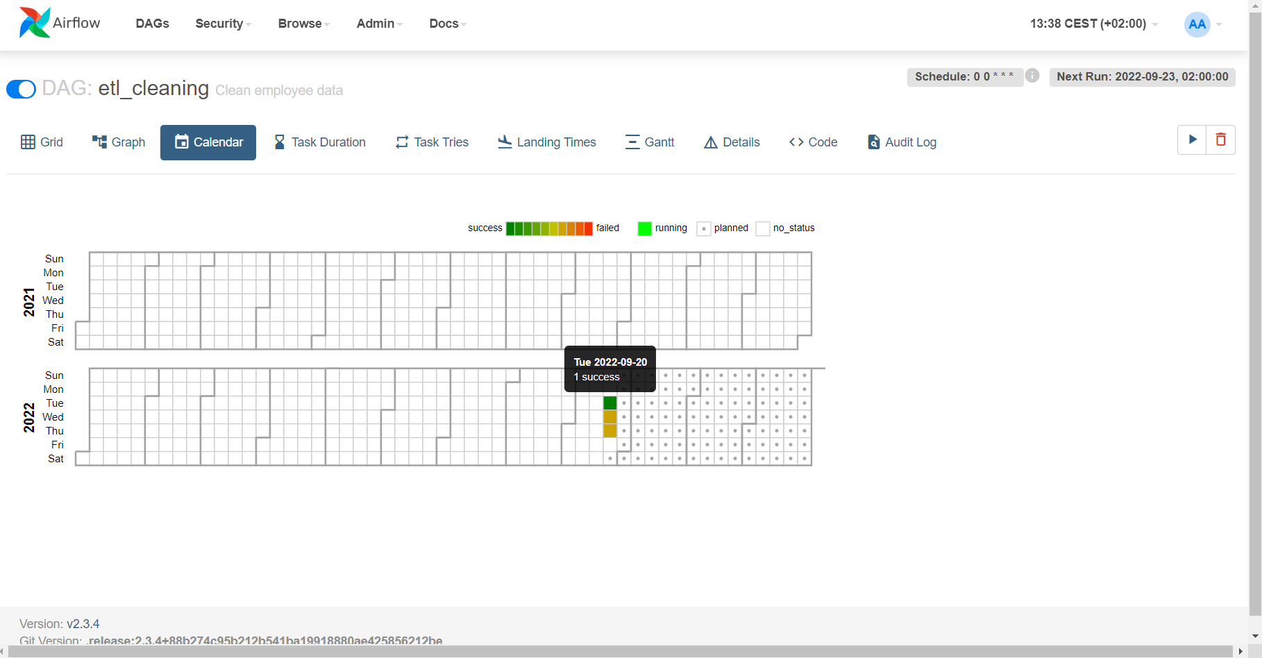
Figure 9: Calendar of DAG executions
Conclusion
In this second part of our blog series about Apache Airflow on Kubernetes, we have seen how to prepare and configure Apache Airflow to run workflows using the Kubernetes Executor. We have developed a simple Airflow workflow, gone through the code to explain its components and its tasks, and finally we have shown how to schedule, monitor, and inspect the workflow execution.
Apache Airflow is a simple yet extremely helpful and powerful framework to organise data processes in your enterprise, from ETL pipelines to simple data transfers and recurring jobs. We hope that this series will spark your interest (if you didn’t know about Airflow already) and guide you in your own workflow developments and deployments.
If you need further support with Airflow, if you are interested in all that this technology can offer, or if you want to see how to integrate it with your existing services and processes, do not hesitate to contact us – our experts will be happy to help you!